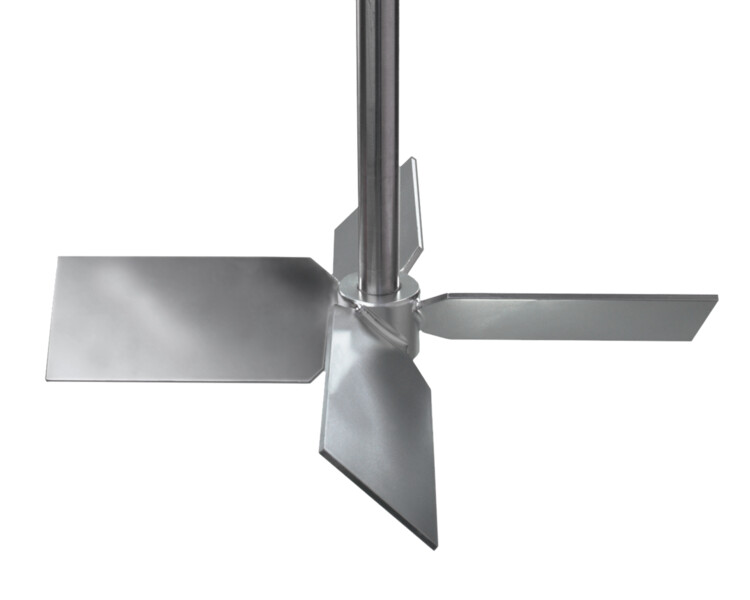
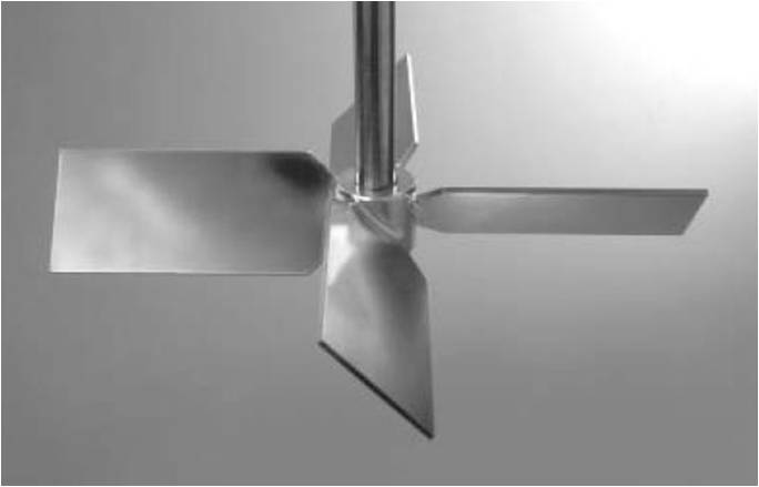
Axial flow pitched blade impellers have one or more paddles. The E-400 Folding Impeller has 4 blades pitched at 45 which fold downwards when not in use.

Structure And Dimensions Of A Rushton Turbine And B Pitched Blade Download Scientific Diagram
Standard pitched six-blade turbine with pitch angle α 45 Pitched blade turbine with diagonally folded blades with various blade number iL 3 4 and 6 blade shape of this impeller type according to Czech standard CVS 69 1043 see Figs.

. 4c and 8 Pitched cylindrical three-blade turbine according to Czech standard CVS 69 10422. The effect of power number in Rushton turbine is dependent on impeller geometry and blade thickness and it is independent on the ratio of impeller International Journal of Pure and Applied Mathematics Volume 119 No. The spinning motion causes some radial flow but the blades pull drilling fluid from the top of the compartment and force the fluid to strike the bottom of the compartment.
Analysis says ok but blade fails. Hub diameter suction diameter outlet width impeller diameter. The angle is normally measured form the horizontal with 45 deg angle blades This type of axial flow creates good top-to-bottom motion in the tank which results in good mixing.
The pitched-blade turbine is a reasonably cost-effective impeller in both turbulent and laminar flow. Moreover it is a cost-effective impeller for solid suspensions. As with axial flow impellers impeller e ffi ciency changes with design.
Pitched blade impeller for effect ive stirring operation in the fluid tank. The blades are pitched at a 4560 degree angle from the vertical shaft. The power distribution of this pitched blade turbine impeller is good for turbulent pulsation.
Model or analysis technique is flawed. Office Phone 45 4411 5400. The basic gate design can be modified to include angled blades on the inside such as in the picture shown to help generate greater axial flow in the mixing vessel.
As a result they have similar mixing characteristics. It is suitable for laminar as well as turbulent flow ranges. Design features a knife extending out from the blade alternating with vertical teeth.
The fluid then flows radially across the bottom of the tank and up the sides of the tank. Design steps for radial and mixed-flow impellers. Product Description As the first evolution of the flat blade turbine the Pitched Blade Turbine or PBT was designed to angle the blades to promote more axial flow than radial.
The Power and Flow numbers shown above reflect 10 pitchdiameter ratio. The angle is normally measured form the horizontal with 45 deg angle blades This type of axial flow creates good top-to-bottom motion in the tank which results in good mixing. Its most commonly used with direct drive mixers operating 900-1800 RPM.
Application of internal or user-defined approximation functions to define impeller parameters. It is also a suitable impeller for applications where the viscosity changes over a wide range causing the flow regime to vary between turbulent and laminar flow. The Rushton or D-6 impeller introduced in the late 1940s creates a pair of vortices behind each blade in.
They convey pumped media in the direction along the revolving axis of the impeller. Impeller and pitched blade impellers Figure-1. The design was based on a Pitched Blade turbine down flow with two inclined blades 45 assuming maximum working conditions.
Common sense tells us that there are four possibilities and corresponding definite conclusions as follows. Perfect for cutting in or shredding rubber wax and other soft materials that tend to gum up on standard impellers. Anchor Propeller Pitched Blade Turbine Chemineer HE-3 Hydrofoil Sawtooth Curved Blade Turbine Straight Blade Turbine Disk Turbine.
Impact of stirrer design and stirring speed on microcarrier distribution. Depending on the angle of the blade pitch 45 degrees being the most common the impeller axial to radial flow ratio can be tuned for the specific process. The design of the PBT impeller provides a combination of both radial and axial flow generates higher shear levels for reactions and provides excellent mixing ability while providing easy cleanup.
Applicable to pumps fans compressors and turbines. At first the pitched-blade turbine Figure 2 was used as an upper impeller. Calculation of the impeller main dimensions.
Each reactor configuration was simulated at different revolution speeds such as 10 20 50 and 100 RPM. This combination provides better overall mixing and creates a higher oxygen mass transfer rate KLa than that of unidirectional marine blade impellers. Axial left and radial flow within a mixing tank.
Internal Dia - 48 cm Height - 58 cm Shell thickness - 06 cm. Viscosity range 100000 cP. Reactor vessel and pitched blade impeller s design and geometry.
The aggressive tooth design of the Type 4 disperser blade works well on ceramics and difficult to de-agglomerate materials. Up to 24 cash back Agitator Design Mech Spreadsheet. The Pitch Blade Turbine impeller is one of the most widely used impellers and one of the oldest designs of the mixing industry.
This impeller fits the most common shaft sizes 58 to 1-14 and comes standard in investment CAST 316 Stainless Steel. Whenever an impeller design is modeled for computer analysis the analyst will generally make a number of assumptions and the validity of these assumptions must be ascertained. Np Graph and User Guide will be provided along with spreadsheet.
The mixing power mechanical design and stress analysis of the agitator were captured as source terms within the FEM models. Lets start the design majority of the design calculations were of thumb rules Dish height 02 x inner dia 02 x 48 96 cm Impeller Dia 40 sweep 04 x 58 192 cm Blade width Impeller Dia 5 192 5 384 cm. The blades on pitched-blade impellers Figure 3 are flat and set at 45 angles which produces a simultaneous axial and radial flow.
The achieved results are shown in three dimensional animations and streamline diagrams. Axial flow impellers are used at high speeds to promote rapid dispersion and are used at low speeds for keeping solids in suspension. Pitch blade impeller design with typical Power Number Np ranging 02 - 20 in a radial flow distribution setup operating directly in the media without circular stator.
The pitch blades turbine is genetic impeller primarily design. The pitch blades turbine is genetic impeller primarily design. Fusion also offers 15 pitchdiameter ratio upon request.
Impeller Diameter 450 mm to 3000 mm Hub with even number of blades are mounted at an angle of 10 to 90 with respect to the horizontal The most commonly used impeller of this type is the four bladed 45 pitched blade turbine. With this detailed modelling the ideal parameters were computed for reactor design. Pitched Blade Diameter 79 mm.
Reactor Vessel And Pitched Blade Impeller S Design And Geometry Download Scientific Diagram
Lightnin A200 Impeller Pitch Blade Turbine

Pdf Study Of Pumping Capacity Of Pitched Blade Impellers Semantic Scholar
Unimix Equipment Pitched Blade Turbine Unimix Equipments Pvt Ltd

Axial Flow Impeller Pitched Blade Turbine 3d Cad Model Library Grabcad

Reactor Vessel And Pitched Blade Impeller S Design And Geometry Download Scientific Diagram

Impeller Types A Rushton Disc Turbine Rdt B Pitched Blade Download Scientific Diagram

A Details Of The Pitched Blade Turbine Pbt Employed B Picture Download Scientific Diagram
0 comments
Post a Comment